2025 update v2: I made a tool that fixes distortions introduced by Intel GPA, and that tool made few sections of this blog obsolete. As such, they’ve been deleted. Old version is still available here.
2025 update. This blog post now also exists as a youtube video. Yes, the video is 1 hour 20, so about twice as long as it takes to read this blog post, but I feel the video shows how Blender works a bit better than a bunch of screenshots.

About a year and a half ago, I decided to 3D print my Guild Wars 2 character because I kinda got into mini painting. I decided to document the process — especially since the reddit guides written by those who came before no longer worked (Guild Wars 2 switching from DX9 to DX11 made them obsolete). Since then, the original blog post has gotten some comments along the lines of “hey, nice tutorial” … which is kinda horrifying, as not only is the post not very tutorial-y, I also had single digit hours of Blender experience at the time (this was disclosed in the post).
I’ve 3D printed two more characters since, and my Blender experience is slightly better than it used to be. Better enough to warrant a rewrite. With my life story out of the way:
-1. Content
- A word about 3D printing methods
- The software you want
- Getting your models out of the game + standard disclaimers
- Making the model printable
- Getting the model printed
- Getting the model painted
And some extra photos of my latest finished piece before we start digging into this. This has been my “work piece”, except that all the screenshots for this tutorial had to be re-created after the mini was printed and painted.


0. A word about 3D printing methods
If you have a 3D printer, you can skip this chapter. If you have a minimal knowledge of 3D printing and intend to pawn off the 3D print job off to somebody else, this section is for you.
At the time of writing there’s two main viable consumer-grade methods of 3D printing.
- FDM
- Resin
FDM printers are cleaner and (depending on the filament) don’t stink. Filament is cheap, but generally aren’t that good with printing details and tend to hate narrow objects — printing anything with cross-section less than 2mm in either dimension is a gamble. Your model will typically come in layers that are 0.1-0.3mm tall (on mini figures, that’s very noticeable. Theoretically you can also print thinner, at 0.05, but you’re just prolonging the printing time while not gaining that much detail), and forget about having anything that’s thinner than about 1mm with your standard 0.4mm nozzle.
But if you want to pawn off your 3D printing to someone else, there’s lots of options and some won’t charge you much. Build volumes of FDM printers tend to be large. 200x200x200 (mm) is common. Larger than that isn’t too rare.
Resin printers are harder to find in the wild. Dealing with resin is messy, resin fumes are toxic, resin is more expensive than filaments. Their benefit is the superior print quality, as they can usually achieve much greater detail than your average FDM printer. Prints aren’t exactly cheap, either, and can get into triple digits per print really fast once you do manage to find a 3D printing service that also does resin prints. With resin printers, it’s really helpful to know someone who’s willing to print you your model for cost of materials and a six pack.
Resin printers generally offer smaller build volumes. Most cheapest common resin 3D printer options can print things that have a footprint of your average smartphone screen, though large-format (200ish x 150ish) also exist.
1. The Software Shopping List
While the heading says “shopping list”, all the necessary software is available free of charge.
- Intel GPA
- I wrote this tool that fixes output from Intel GPA to some degree (more on it later)
- Blender
- PrusaSlicer
All three have alternatives, but if you know of them you probably don’t need this post to teach you how to use them.
Once you install Blender, you should also install 3D tools addon. Open Blender, go to Edit -> Preferences, select Get Extensions in the side bar, search for 3D print toolbox, click Install.
2. Getting Your Model Out
At this point, we need some disclaimers (especially if you want to also use this on games other than Guild Wars 2).
Using Intel GPA suite might be a bannable offense in some multiplayer games. You’re doing this at your own risk.
Intel GPA extracts models by intercepting data your game sends to the GPU, which is the same method used by some cheats. As a rule of thumb, if your game appears on ReShade’s Games to Avoid list, you should stop reading right here and now because it’s pretty much guaranteed this method will result in a ban.
Conversely, if your game tolerates ReShade, you are probably fine (but I’m not going to vouch for it). When in doubt, try with an alt first.
At the time of writing, Guild Wars 2 does not appear to ban you for doing this (at least not in PvE).
Second thing — per several comments both here and on reddit, game mods can cause either games or Intel GPA to crash while capturing the models. If the game crashes when you try to extract models, try disabling mods.
When you launch Intel GPA, you get something like this:

Navigate to your game’s executable (the three dots button gives you a GUI browser) and then click launch.
Once launched, find yourself a quiet corner on the edge of a map. You need two things:
- A character that you want to export
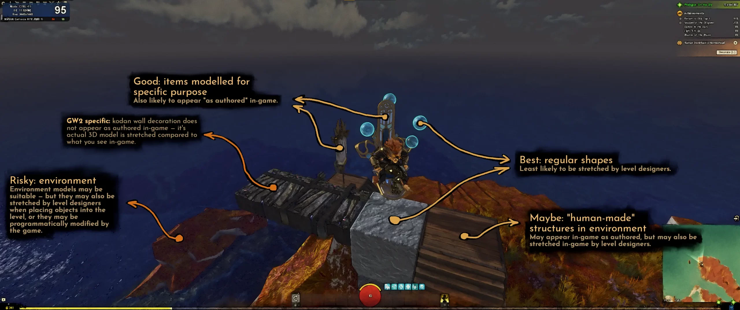
- A landmark. This one is optional — you only need this if you want your character to appear to-the-micron exactly as it appears in game. If you’re fine with minor inaccuracies.
“Landmark” can be any object that is not rigged or animated or otherwise deformed. It needs to be static, it needs to be made out of one contiguous mesh, and it needs to be a 3D model that either game or game designers didn’t stretch after importing it into the game engine. In order to make game environments not look overly samey, game developers often tend to randomly stretch certain objects in order to hide the repetition. Objects that can be stretched without you noticing — including, but not limited to, trees, terrain, buildings, and especially rocks — those object are a bit risky to use as your landmark. On the other hand, boxes and anything else that’s a perfect cube or sphere, or carefully sculpted models (e.g. lamp posts, statues, other models with meaningful artistic detail) are a reasonably safe bet for your landmark.
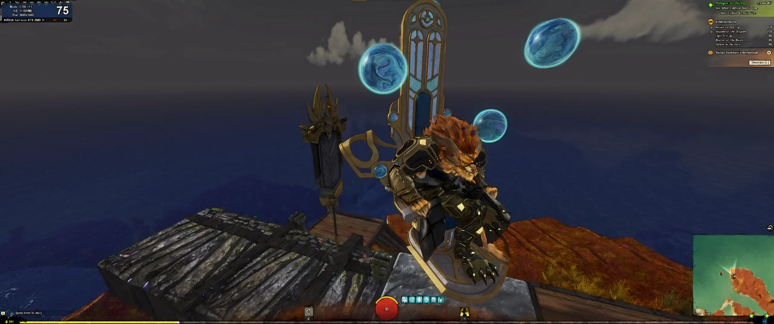
After you picked what you want, strike whatever pose you wish and then trigger the capture (by default: CTRL + SHIFT + C). You want your character to take as much of your screen as possible, while keeping at least part of your landmark visible.
After you’re done, you can close the game.
Finding your mesh in the capture
After the capture, you can see that some new things appear in your GPA window:

Double-click any of them (but preferably the one you need, the captures are ordered from newest at the top to the oldest at the bottom), then wait. Graphics Frame Analyzer doesn’t open instantly — it can take up to half a minute even on a decent hardware, possibly longer on a toaster.
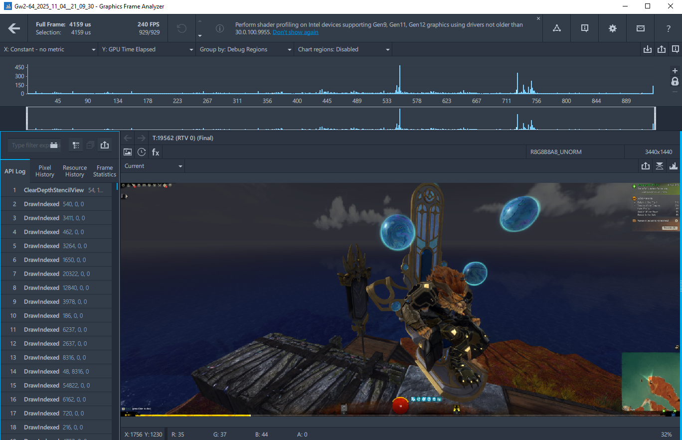
You get a window like this:
There’s a few different ways you can go from there. The most optimal path depends on what you want to achieve. If you want to get some models for cosplay, or if you want to rig and animate your character, then you don’t need (nor want) to preserve your character’s pose. If you want a mini to 3D print, you probably do want to preserve your character’s pose.
Getting your meshes
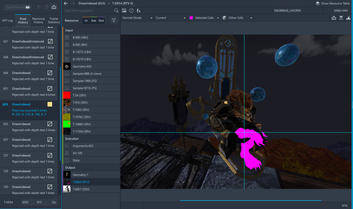
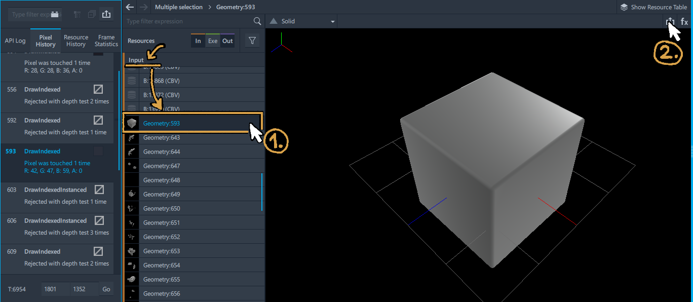
Click on your character on the screenshot. This will switch the first sidebar to the “Pixel history” tab, which will show all the Draw calls responsible for the color of the pixel you clicked on:
With most modern games, the first time you click on the screenshot, you will only have one option to click on. If for some reason you have more than one, you should click the one that matches the color of the pixel you clicked on.
Clicking on the DrawIndexed call in the pixel history will open the second sidebar and highlight the 3D models that the DrawIndexed call is responsible for putting on your screen. The first time you do so, the entire screen will get highlighted in purple.
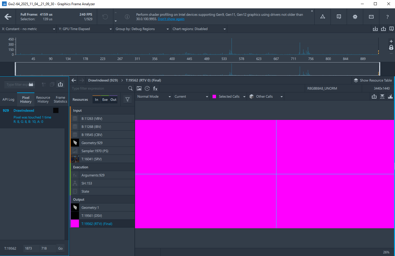
This is expected at that point and happens because game engines render their frames in stages: by default, Intel GPA shows you the final result, but your character is drawn on one of the first steps. So how do we reach the step on which our character is rendered?
You may have noticed the second sidebar appear on the left. It has three sections: Input, Execution, and Output. Input section includes all the ingredients that go into making the frame in current step, we don’t care about Execution, and Output section contains the cooked lunch.
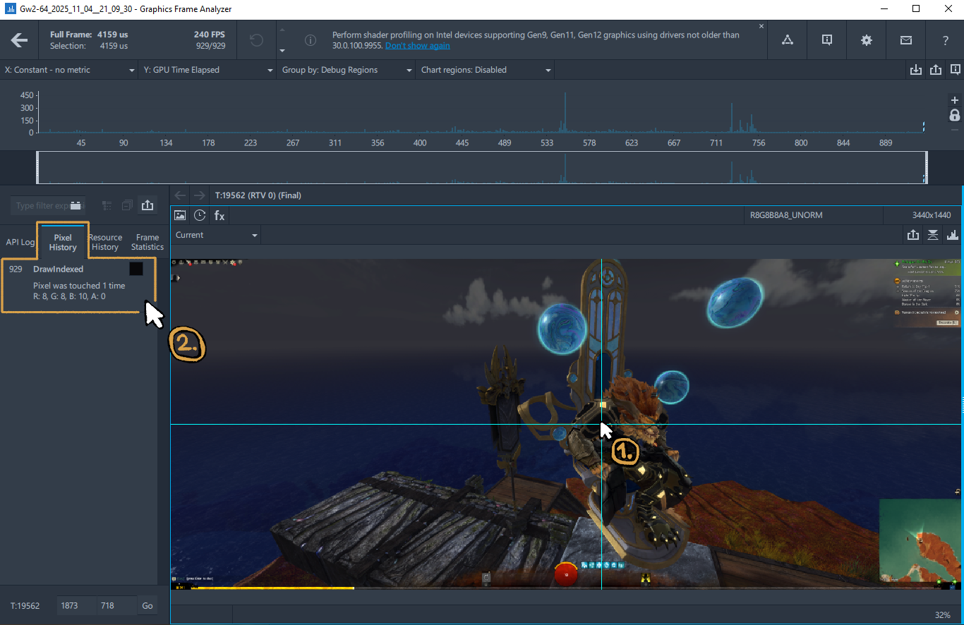
In the Input section, find the item that has the thumbnail that looks the most like the screenshot and select it ①. Then, click on your character ②, observe how Pixel History panel contains a different DrawIndexed call, and then click said DrawIndexed call. ③.
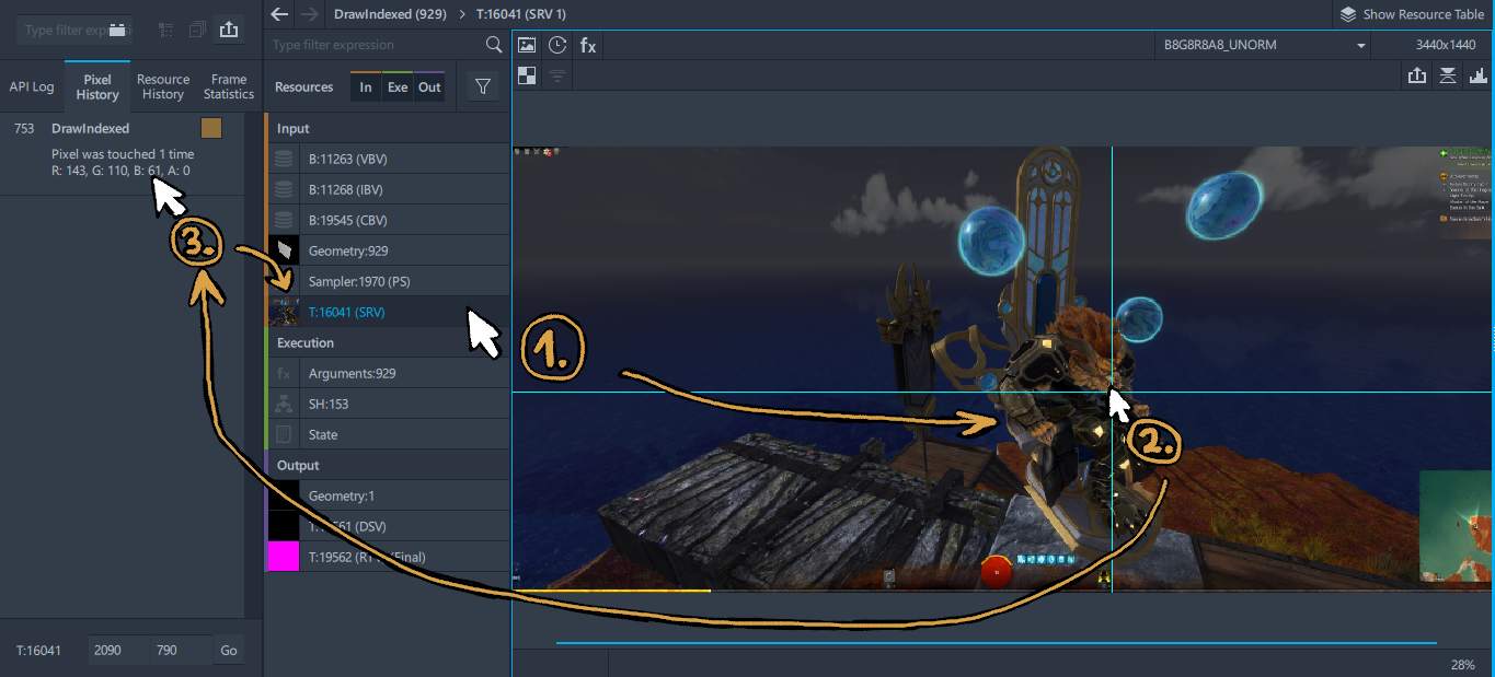
Do note that if you’re doing that for modern games with latest rendering engines, intermediary steps that you’re interested in will not look like the final result that you observe in game — they may be significantly darker or even unlit (or even in false color because you’re looking at a normal map — but don’t complicate your life like that).

—
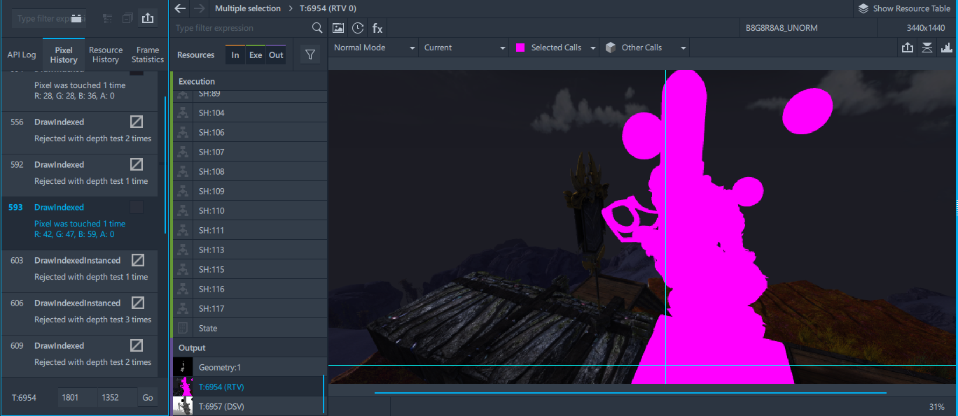
You will know that you reached your destination when you click on your character and your Pixel History tab looks like this:
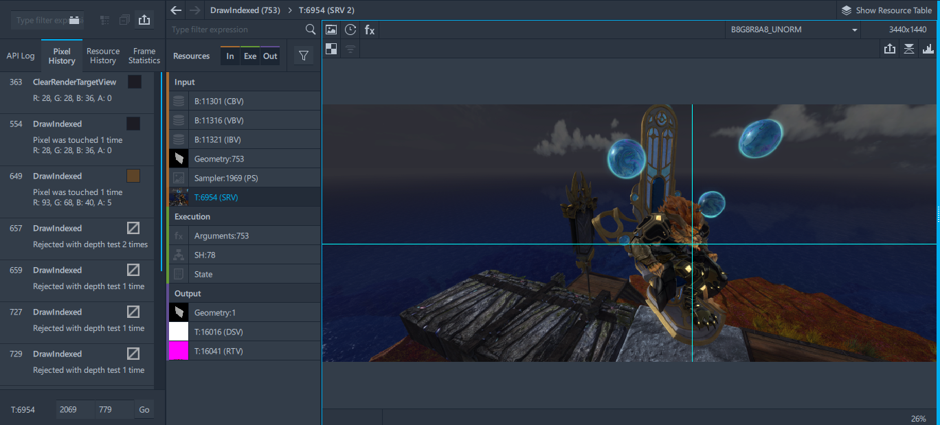
When you have multiple DrawIndexed calls, then the correct option is the first option where the square next to DrawIndexed call has the same-ish color as the pixel you clicked on:
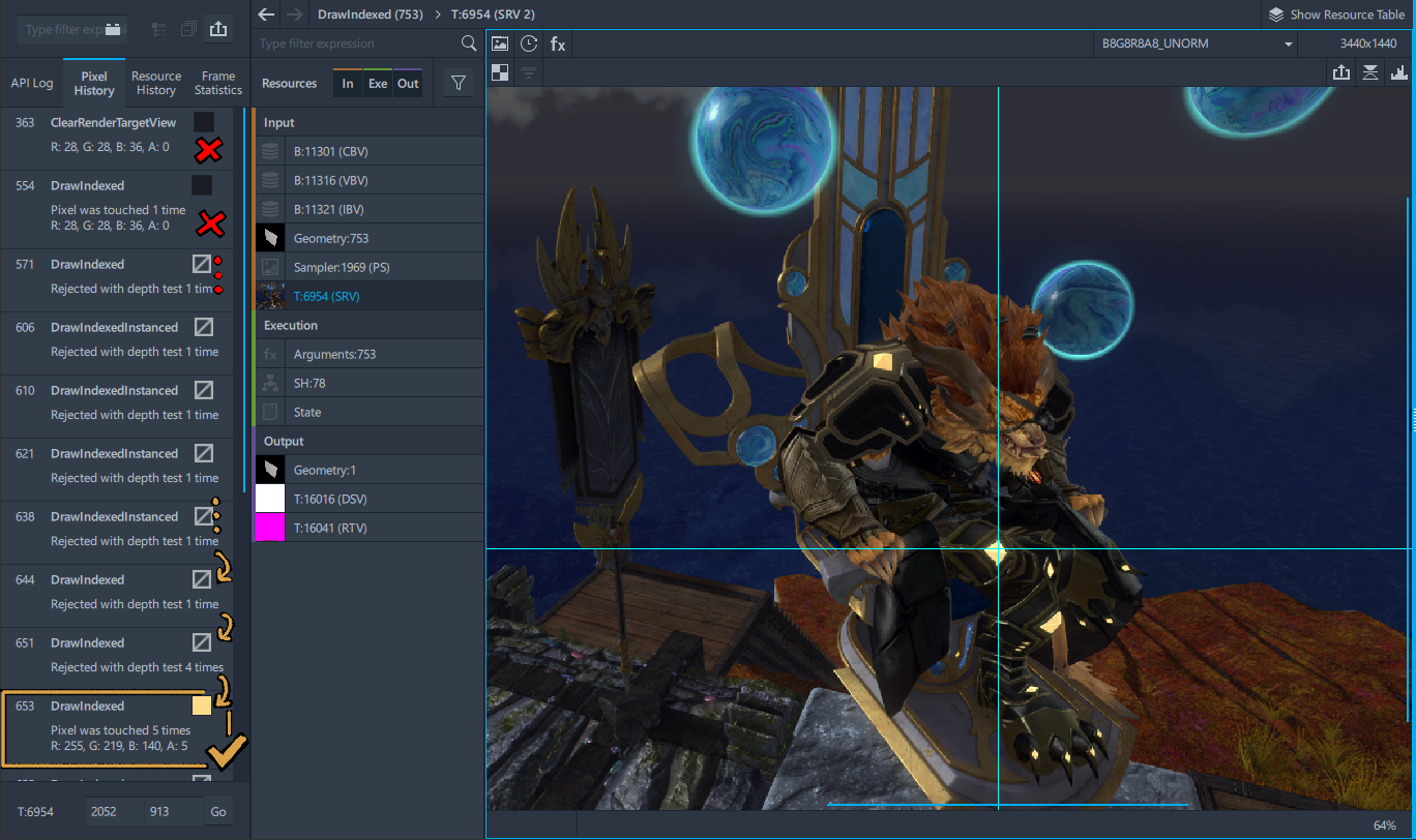
Clicking that option should color your character purple:
However, you may have noticed that not everything is highlighted. That’s because your character is made from multiple meshes.
You can add the rest of the character by pressing Ctrl on your keyboard, clicking a bit of your character that isn’t highlighted, and then control-clicking the accompanying DrawIndexed call in the Pixel History tab.
Repeat until your character is completely highlighted. Don’t forget to select the landmark.
—
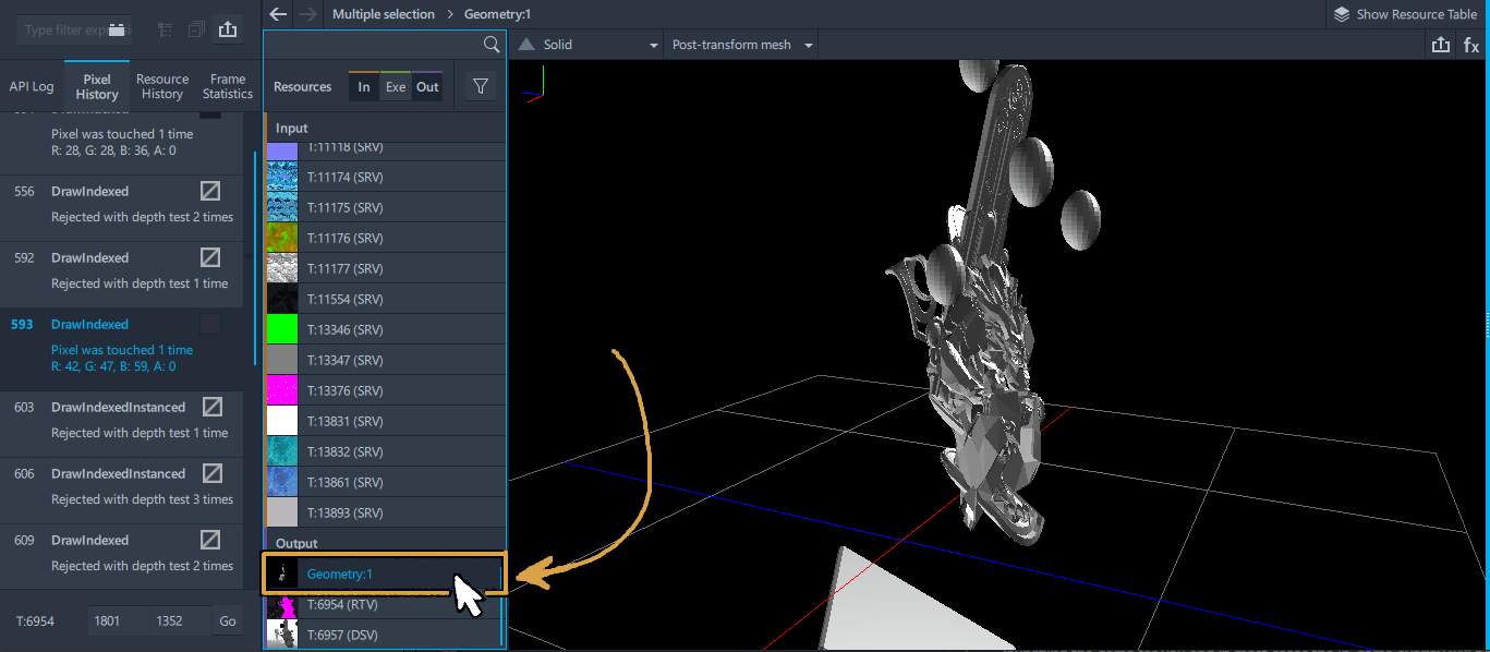
Verify that you did actually select everything by switching to Geometry option in the Output section, and give your character a spin.
If your character appears to be missing an item that is hidden behind them in the screenshot, you may switch to API Log tab. You will notice that DrawIndexed calls responsible for your character’s existence on screen appear relatively close to each other. You can try control-clicking a few nearby DrawIndexed calls and observe whether anything gets added to your character or not. If this results in unintended items appearing on the preview, you can always remove them by control-clicking the offending DrawIndexed call again.
Then, export output geometry by clicking the output geometry.
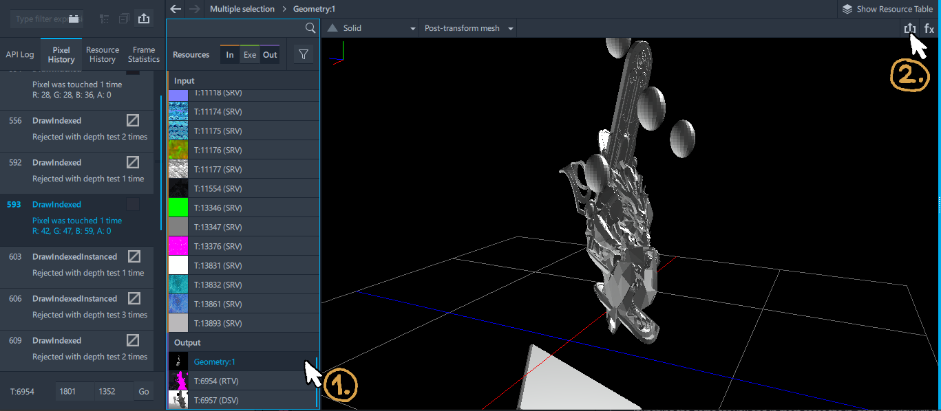
.obj to somewhere you can find it.Lastly, scroll back up to Input section, find your landmark’s Geometry entry, and export it. Do note that your landmark isn’t guaranteed to appear as the first Geometry item in the output.
Exporting for purposes other than printing your mini
If you’re exporting stuff for your cosplay project, or if you want to have your characters in T-pose in order to animate or pose them manually, you probably want to skip exporting things from Output section and instead export ALL geometry items from the Input section instead.
If that’s the case, you also don’t have to export your landmark, as landmarks are only used to fix the exported output.
This was the easiest 10 minutes of the whole process.
Making Your Model Printable
The model you exported has some problems that make it not the most printable. Some more obvious than others.
You probably noticed that your character appears squished, and we don’t want that. Your model also contains gaps and other stuff that 3D printers don’t always like. This means we’ll have to open Blender and fix those issues.
Unsquishing the model

♫♫♫ Tell me everybody, now, what do you think of that? ♫♫♫
If you did the Intel GPA step as instructed, your model should be squished in a very particular way.
When you’re playing a game, game engines convert coordinates of objects into something suitable for graphics card to work with. By convention, everything you can see on screen exists inside a cube from (-1, -1, -1) to (1, 1, 1) — though certain graphics APIs and/or game engines may do things slightly differently.
This means that what your monitor displays as, say, 3440×1440 rectangle, your GPU perceives as 2×2 square. In order to undo the squish, we therefore need to stretch the square back into the rectangle.
To be completely honest, you don’t need to do any fancy math. You can import model in Blender, press Num 1 for front view, press S X and drag the mouse around until your model looks good from the front. You can get the exact amount by taking your in-game resolution and dividing width by height. Result is the correct scale factor for X axis. For 16:9, that’s 1.78. For 21:9, that’s 2.39 or 2.370 Then, you press Num 3 for side view, press S Y, and drag the mouse around until your model looks good from the size, and you’re done.
But if you want your character model to appear exactly as in game, you can do some math in order to achieve that — assuming, of course, that you picked your landmark correctly. Because I’m occasionally doing these things a lot, I decided to write myself a tool that automatically corrects the squish for me and incorporates some other QoL improvements. Here’s the link. Since we exported our landmark object both in squished and unsquished version, we can use some maths to calculate exactly(ish) how squished our character is.
You just have to drag the files onto the fields of the webpage:
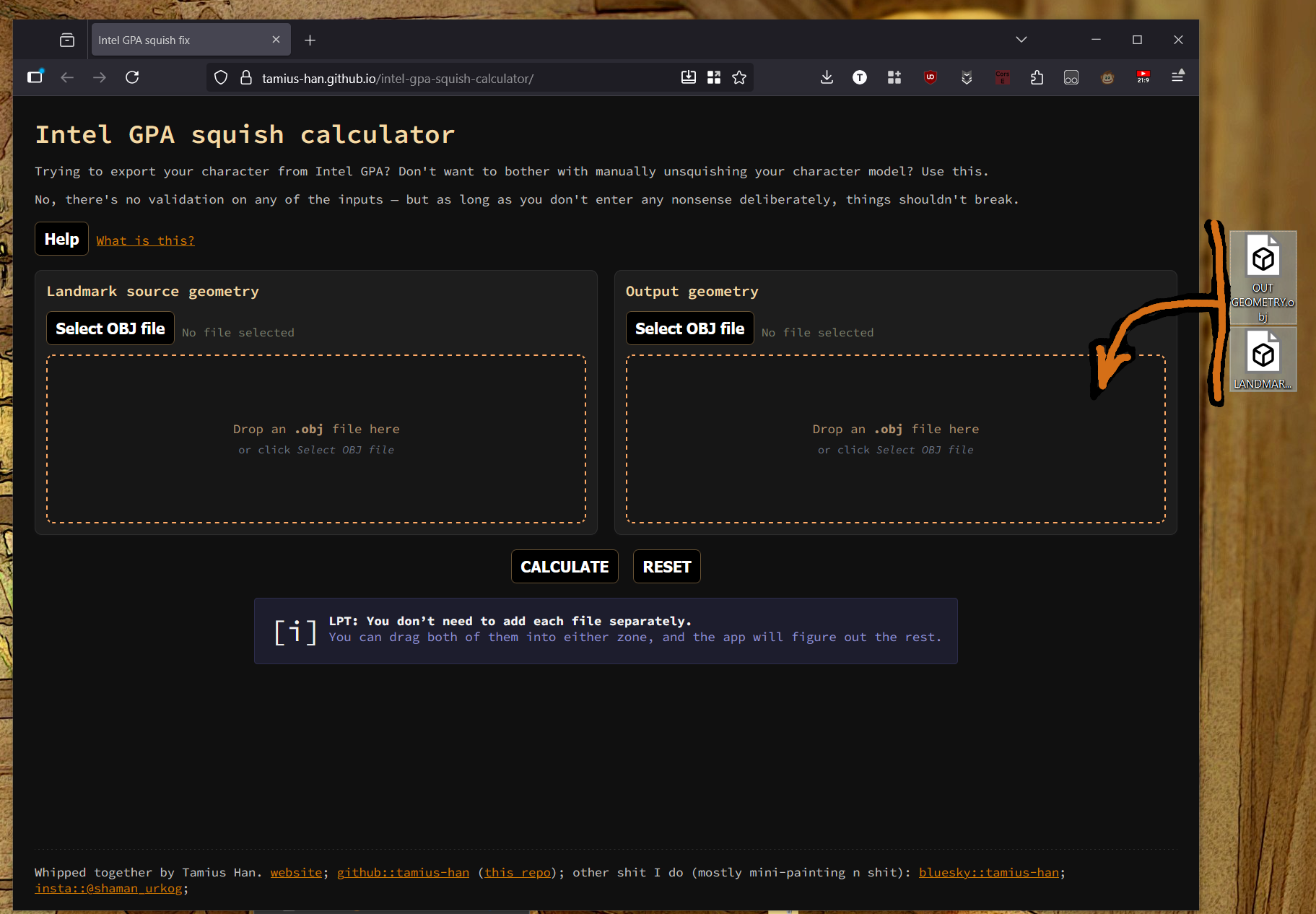
As soon as you’re done, the page will automatically calculate correction factors. If X factor matches your in-game aspect ratio, then the conversion likely happened without issues. Otherwise, you may need to pick a better landmark.
But if everything is fine and you get that “fix and save” button, you can just click it in order to save the fixed version. If your landmark is character’s weapon, then also untick the “remove landmark from output geometry” checkbox.
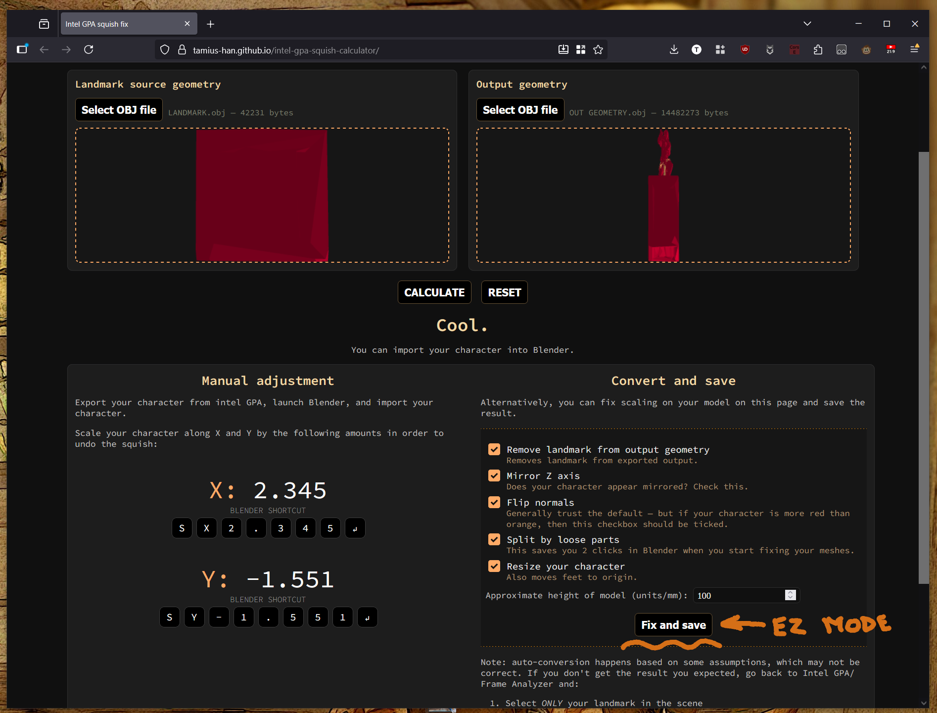
By the way — this conversion page runs entirely in your browser. If you download the project from github, this converter will work without internet connection.
How 2 Blender for absolute beginners
If you’re new to Blender, this resembles what you’ll see. Your first steps are:
- Ctrl-click ‘camera’ and ‘light’. We don’t need those two things. Press ‘delete’ to get rid of them.
Strictly speaking, we don’t need the cube either — but it’s gonna be mildly useful for the next 5 minutes. You can leave it for now, as it makes it easy to see which zoom level comes with millimeter squares on the grid in the background.

- Click the Viewport overlays dropdown and check the Face orientation checkbox. The cube should turn blue. From now on, blue means good and red means bad.

2025 update: Blender 4.4 came out, and changed a few defaults. When you check ‘Face Orientation’ box, the model will remain gray on the outside. However, as said before: seeing red (when not clipped into the object) still indicates a problem.
I ain’t gonna go and update screenshots, though. Unless sections require corrections for other reasons.
Now it’s time to import the .obj file we saved in the previous chapter. Once our model has been imported, we should stand it upright and scale it to the size we want.
By default, Blender works on the scale of 1 unit = 1 m, but 3D printer assume that 1 unit = 1 mm. This means that every time you see 1 m in Blender, you’re looking at 1 mm once printed. You could configure that away if it bothers you, but it hasn’t really been a problem for me.
If you haven’t used Blender before, your favourite keyboard friends will be:
S— resize (scale)r— rotateg— move (grab)
You press the key to enter resize/rotate/move mode. While these modes are active, moving your mouse around will enlarge or shrink the object. When you reach the desired size, position, or rotation, left-click to finish the process.
While rotating, resizing, or moving, you can also press x, y, z to limit movement / resizing / rotating along/around the respective axis, and shift-x, shift-y, shift-z to limit movement/resizing along the plane perpendicular to the respective axis.
If you want to resize (or rotate, or move) the object by a given factor, you can also type out S <factor> and press enter, e.g. S 2 [enter]. This will make the object twice as large (along each dimension).
Then, there’s:
Num 1,Num 3,Num 7for front, side, and top viewNum 9— look at the model from the opposite sideNum 4,Num 6,Num 2,Num 8— rotate the camera around the model along the horizontal/vertical axis.Num 5switches between orthographic and perspective camera
I hope you’re not one of the peasants who think numpad part of the keyboard is optional, because it’s really über-handy when you’re doing anything in blender.
If numpad doesn’t exist on your keyboard, you can use this gizmo instead:

Another thing we need to cover upfront is movement:
Middle click + dragwill rotate the camera around the modelShift + middle-click + dragwill move you across the spaceMouse scrollwill zoom/unzoomShift + `turns on Walk/Fly mode. This allows you to move around the scene withWASD(+Q/Efor up and down). Left-click while in the mode puts the camera at your current position. Escape resets camera position to where you were before you entered the walk/fly mode.
That about covers the basic basics. Now you can resize your character to the size you want (I usually go for 100x100x100 mm bounding box), and rotate it upright.
When rotating your character, your character is rotated around an origin point. Said origin point may be far outside your character, which will cause the model to be rotated in unexpected ways.
If you used the squish calculator earlier, the origin point should be approximately at your character’s feet, which is probably the most convenient position for rotations and scaling. But if for some reason the origin point of the character is widely outside of your character, you can fix that by right-clicking your character and selectubg Set Origin -> Origin to Center of Mass (either option is fine).

Low-poly: Getting the “minimum viable model”
In order for games to run as fast as they do, game engines and game designers tend to cheat a lot. Game objects — especially characters — often aren’t solid 3D objects, but a collection of triangle sheets that have no volume. When you’re playing a game, you aren’t going to notice this (unless you look really close), but your 3D printer will.
Thus, we need to ensure our character consists of a single mesh that has absolutely no holes in it.
There’s few other things we need to keep in mind:
- all walls should ideally be at least 2 mm thick
- you can go thinner than 2mm if it’s an emergency, but don’t go under 1mm thick.
- Yes, even if printing resin
Or at least that’s the advice I got. Sounds reasonable, so I’m going to pass it on.
But back to our character model.
When we extracted the character model from the game, the meshes the character is made of got broken into individual triangles. This is bad, because it makes cleaning the model up much harder. Fortunately for us, we can fix that — in two ways.
Option A: export the model as .stl and then re-import it again.
Option B: add weld modifier, mode All, with the smallest positive non-zero number possible in the Distance field:

Check that this didn’t delete any triangles you didn’t want to vanish. Apply modifier, then Tab to switch to edit mode.
Removing unnecessary parts
Edit mode has a toolbar to the left. By long-pressing the top option ①, you can choose the kind of select tool you want. Box select is adequate, but you can probably do better by using lasso select option. You can also choose whether you want to select polygon vertices, edges, or faces ② (keyboard shortcuts are 1, 2 and 3 respectively — get used to them because they’ll speed up things a lot).

—
Before continuing, verify that weld modifier succeeded in joining triangles into meaningful meshes. Select any single face, edge, or vertex and press Ctrl+L. If this expands the selection to more than one triangle, then weld modifier did its job and we can continue.
Then, press A. This should select everything (and if it doesn’t, press A again). Right-click anywhere and choose Separate -> By Loose Parts in the popup that appears ①. This should turn your one object into a lot of objects ②.

At this point is to eliminate small meshes that we don’t want to deal with. Most notably, anything that’s
- made up of single-digit number of polygons
- any small details that don’t have any width to them
- anything that you can tell is too small to print. If it’s nowhere close to being at least 1mm in every direction, it has to go
- honestly just use common sense. If you remove a mesh and you don’t think it has a meaningful effect on the appearance of your character, then it needs to go. If it’s less than 1mm along any axis, and if it has less than 1x1mm contact with the mesh next to it, it’s gonna be faster for you to just re-create that later.
Be careful because skirts and below-waist parts of trench coats aren’t always a single mesh — they could be made out of two meshes. Spearmarshall medium (on picture) doesn’t do this, but Rubicon does.

While you’re busy shift-clicking:
If you make a mistake and lose your selection — in Blender,
Ctrl+Zalso undoes any changes to your selection. If you select 69 meshes and then accidentally click while not holding shift — no need to re-click all 69 individual parts, justctrl+Zit.
Once you selected everything you want to keep, right-click and select ‘move to collection’. Choose the ‘new collection’ option in the popup that appears, and name your collection whatever you want.

Then, hide everything that’s not in your new collection and make sure everything is visible in your new collection. That allows you to see if you missed anything important:

If you are, hide your new collection, unhide your old collection, and repeat this process until all the important bits of your character are in your new collection, and the old collection contains just the tiny bits you don’t want to deal with.
For my specific case, the division between things I’m willing to put up with and the things I don’t looks something like so:

Key takeaways:
- yes, I do keep some of the tiny meshes — (spikes on the hand armor, jewelry, teeth). They do quite significantly contribute to final appearance, but they also have some relatively significant volume.
- I can hear the “yeah but net is a significant part of Spearmarshall’s armor” in the distance, and that’s correct. However, the mesh is nowhere near printable — certain parts are too thin or too twisted or turned inside out, with unholy amount of self-intersections. It’s gonna be a nightmare to boolean. It’s much easier and less effort to re-create the mesh from scratch, than it is to ensure the existing mesh is gucci for print
- I’m not willing to put in the effort to add backpack straps to the model (at this point), so backpack gotta go
- The bits at the bottom of spearmarshall armor’s skirt are zero-width and thus non-printable, you can see those bits are very 2D from the picture. You’re better off recreating those bits by hand if you want to have them. It’s gonna be much faster.
Fixing the geometry
Now it’s time to do something about the red bits.
The color of objects represents whether we’re looking at the inside face or the outside face. Since we’re looking from the outside, we should only be seeing blue faces. There’s four reasons why you could be seeing red that can be relatively easily fixed:
- the object has no volume, and consists of a single polygon sheet
- the object is open on one side (solution: fill the gap)
- the object is inside out (solution:
shift-nrecalculate normals) - the object self-intersects in a way that part of the object is inside-out

Example of latter is on the under-belt portion of the Spearmarshall’s armor — this red bit here:

This is solved by going into the Edit Mode, pressing 3 to select faces, and then selecting a ring of blue faces around the red bit like so:

We delete the faces (Delete). This leaves us with a gap in the model, which is bad. We don’t want holes, so we need to fill that. Press 2 to select edges, Alt + click to select all the edges around the hole (If alt + click does not select all the edges, you can add additional sections by pressing alt + shift + click), and then pressing F, followed by T. The hole should be filled and the fill should now be made of triangles:

Note that this action left us a bit of orphan faces we don’t want anymore. We need to find them and delete them, which is an exercise for the reader.
Example of “object that’s open on one side” is on legs, arms, and whole lot of other places, actually. Select the guilty mesh, press 2 while in edit mode to select edges, Alt + click on an open edge.

Press F, press T. Done.

Repeat for all other models.
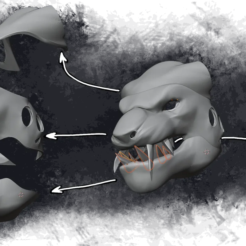
Now we’re getting into trickier bits. Hat is the case of being a polygon sheet without volume. This requires a little bit of thinking to solve, as it varies on case-by-case basis.
Our meshes should not have any inside walls, and there should be absolutely NO situations where more than two polygons share an edge. If you have more than two polygons along the same edge, you either have an inside wall, or a bit of geometry that’s a bit of red in the sea of blue.


The correct approach is to identify which edges are shared by more than 2 polygons, and deleting the offending polygons. Usually, that’s blue polygons that share a border with reds when watching model from the outside:

Select the offending polygons and delete them (Delete -> Delete faces). After deleting, you may move individual edges, polygons, and vertices around to achieve a better shape (to your taste). After you’re done, select the faces that were red initially (do not select red faces that were under the blue faces you just deleted) and press E to extrude. You can eyeball that “emergency 1mm thickness”, or you can press Esc. This will give you a dialog popup:

You can use the popup to move up exactly 1mm by adjusting the appropriate slider. You probably want to check the Dissolve Orthogonal Edges checkbox as well, because if you don’t, you may end up with inside walls:

We also see that extrude only moved our polygons up and created walls, but it didn’t fill the bottom for us. One of the walls that were created by extrude will become inner wall once we fill the gaps. We delete this wall:

Then, we connect bottom faces of the hat on the inside end with bottom edge of the outer brim:

You then fill the hole (Select edges with Alt-click, F, T), and do the same thing on the upper edge.
After you’re done, parts of the hat will still be red. At this point, you press A to select all vertices/edges/faces of the mesh, and Shift + N to recalculate normals. If your mesh turns blue, you’re gucci. If it stays red (or if it becomes redder, but not completely so), then you probably have an unfilled hole somewhere in the mesh, or an inside wall. Find and fix.
Remember to do this for every individual piece in isolation. Just because something looks okay when you see all the parts, that doesn’t mean all the parts are okay — and if some parts aren’t okay, this could be problematic later when we try to join everything together.

Check that geometry is actually fixed
So here’s a (not so) fun fact: just because you can’t see the red, it doesn’t mean everything is cool. After fixing the “obvious” problems, you should also check if the problems are really gone with the 3D Print Toolbox addon.
When you installed 3D Print Toolbox addon, it should have added a new, 3D Print tab to the right side of the viewport. Click the tab, expand Analyze section if necessary, and then click the Check All button.

If you click it, you will get a detailed report of all the problems with your model. If you’re in edit mode, each problem in the result will be a button. Clicking the button will select all the problematic edges or faces.
There’s a few that you can ignore, and a few that you can’t. The non-ignorable problems are, as follows:
- Non Manifold Edges — they usually indicate a hole that you missed, or cases where the same edge belongs to more than two polygons (aka “the hat problem” from earlier). If you don’t fix this, you will experience problems down the line.
- Intersect faces — we already said self intersection is bad, but fixing this one is pretty manual
- Non-flat faces — you fix this issue by clicking the button and pressing
Ctrl + T.
You can ignore everything else (except Bad Contiguous Edges, but I haven’t seen that one in the wild yet).

Yes, this screenshot was added into this article after Blender 4.4 came out, whereas most of this article was written using Blender 4.2.
If you explore the options offered by 3D Print Toolbox, you might notice that ‘Clean up’ section offers a temptingly-named “Make manifold” button. In my experience, ‘make manifold’ button is only rarely the “fix this for me because I can’t be bothered” button. In my experience, “Make manifold” has been more likely to destroy things than it was to fix them. You can try if it fixes the issues for you, but keep that Ctrl + S and Ctrl + Z handy if you go that route.
Ensuring proper thickness
Once you’ve filled all the holes, it’s time to ensure sufficient thickness everywhere across the model. This one is simple: you go around model in front, side, and top view and use Blender’s background grid to find things that are thinner than 1-2 mm. Once you identify such parts, you enter into edit mode, set select mode to faces (3), and select all faces along one of the sides of the part. Angle your camera so you’re looking at the part from the side. Press G to move all the selected faces to the desired position. Click to make them stay there.
Pressing X/Y/Z (and Shift–X/Y/Z will, as usual, limit the movement of faces along the world x,y,z axes.

This isn’t always possible. Sometimes, faces of the side you want to move will share edges with the side you don’t to move. That’s when you extrude the faces (E).

The problem with extrusion is that it can only move your faces in one direction you have relatively little control over … and it can mess up parts of your model a bit if you aren’t careful. But if extruding puts your faces in places where you don’t want them to be, you can still move them around by using G to move or S to scale.
With fingers, you probably want to make them thicker without making them longer. You could select each edge loop that goes around the finger and make it bigger, but that would take a lot of time. Quicker approach is to enter Sculpt Mode ①, choosing Inflate/Deflate tool ②, and then clicking the fingers until they get big enough (but they shouldn’t intersect).

If the process is too slow to your liking, you can also adjust how strong the tool is ③ — and if you ever need things to shrink instead of inflate, that’s what the +/- buttons ④ do.
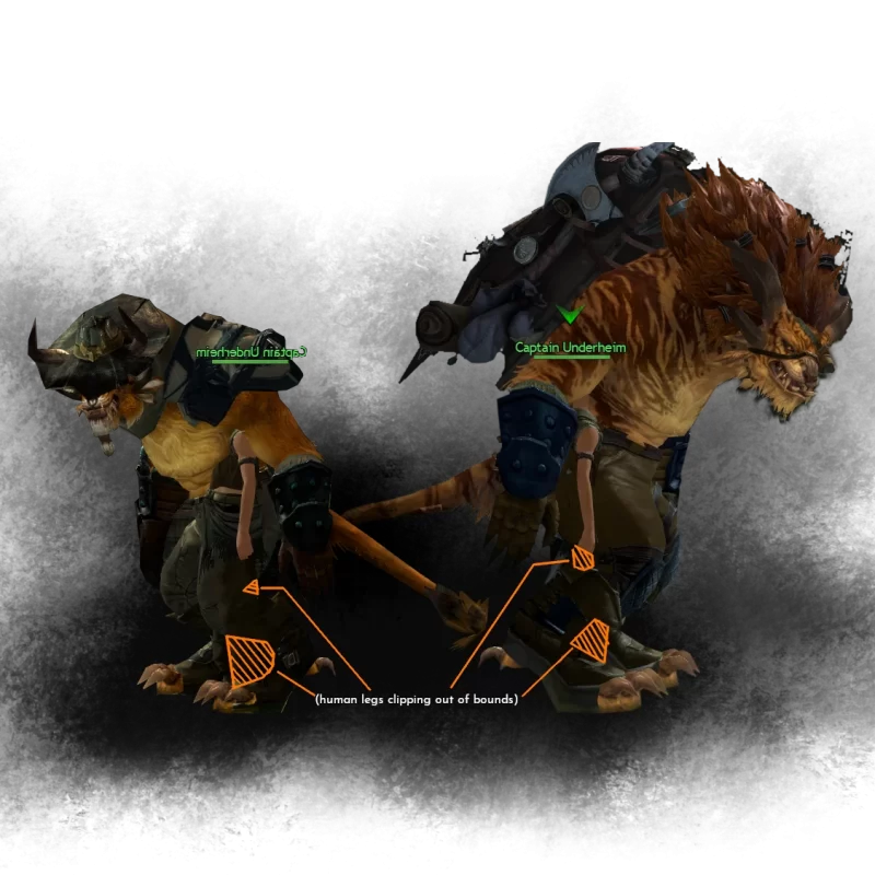
Other minor things
Does this armor clipping bother you?

Things like that aren’t illegal to fix. Enter object mode, select the clipping object, and move G and rotate R it a bit until you find something that works. Sometimes (if the armor comes in enough distinct pieces), it can literally take less than 5 minutes to fix — and if the object rotates around a point you didn’t expect, you can right click -> set origin -> center of mass.

This is much better, and it didn’t cost a lot of time.
In some cases, though, you might need to mess around with the lattice tool a fair bit.
Merging it all together
In order to print the model, it needs to be in one piece. If you keep all the relevant meshes in a single collection, this is pretty straight-forward.
Enter the object mode and draw a small cube, and move it so that the cube is completely, 100% inside your character.

Then, add a boolean modifier to the cube. Boolean should be set to Union, operand type should be set to Collection, and Collection should be set to the collection that you moved your fixed meshes to:

Once you do so, hide everything except the smaller cube. If you can still see your character in blue, then congrats: you probably have a model that you can print. If you don’t see your character in full, or if you see a cube, then something went wrong. Possible reasons:
- You didn’t fill all the holes in all the meshes of your character
- Blender booleans aren’t always reliable
Possible fixes:
- Find the problematic parts that you missed
- Try joining parts of your character in smaller steps — e.g. try joining just the legs, and just the arms, and just the head, and just the rest of the body. This will make it easier to identify which parts of your character are causing problems.
Speaking of that last point: there is some benefit to keeping your mini in multiple pieces — e.g. separate piece for legs, arms, head, and the rest of the body. You might want to keep your mini in multiple pieces if:
- you don’t have access to a a 3D printer big enough to print the entire mini in one piece
- you want to put shinies (LEDs) inside your mini
- you plan on painting your mini and don’t want to deal with the difficulty of painting hard-to-paint corners
- you want to sculpt back the details and have a mid- or especially low-range PC.
If everything looks fine, apply all the modifiers. Now you can export the model as stl and head over to the TODO LINK — although you probably also want to create a base for your mini. Make sure that you select the smaller cube (which should now look like your character), and that you check the Selection only and Apply Modifiers checkboxes in the Export STL dialog window:

Exporting multi-part prints
If you decide to split your mini into multiple parts, you need to think about where you want one part end and the other begin. In general, you want to cut along a sharp edge in order to make seams less obvious.
Step number one is to appropriately sort character meshes into different collections for each separate part you want to print. Meshes that cross the plane where you want your cut to be should be in both collections.
Step number two is to create a cut. Use the Add cube tool from earlier and create two cubes — one above the place where you want your cut, and one below. Scale and position them so that the part you want to cut goes completely through the middle. Use boolean modifiers to subtract lower cube from the upper part, and upper cube from the lower part. If upper part has any unwanted geometry remaining below the cut, or if the lower part has any unwanted geometry remaining above the cut, tab into edit mode and delete unwanted geometry. To make things easier, you can select a small handful of points of the unwanted geometry and press Ctrl + L to select everything that’s connected to the selection.
After you create the cut, also make sure that parts don’t overlap. If two parts overlap, they won’t fit once printed. If you find your parts overlap, use boolean modifiers to subtract smaller part from the bigger part (or the other way around, if you think it’ll look better).
Step 3 is to create some pegs and holes. While circular pegs and holes often are tempting, it’s generally better to have rectangular or at least elliptical pegs.
First, decide which part gets a peg and which part gets a hole. For strength, it’s usually better to have the peg on the smaller part, and hole on the bigger part. Then, draw the “peg” box. Start drawing on the surface, and extend the box about ~3-5mm from the surface. Once the box is drawn, move it slightly into the mesh of the part that will receive the peg. After moving, duplicate that box and make it slightly bigger. Try to make it 0.25-0.5 mm wider on both sides, and up to 0.25-1mm longer. The second box is your hole box.
Pegs should also always be as wide as possible.
Use boolean modifier to add (union) the peg box to the part that should have the peg, and subtract the hole box from the part that should have the hole. Ensure that your peg and hole are sized appropriately — you want your peg to be at least 2mm thick, and you want the walls around the hole to be at least 1mm thick.
Designing the base
You don’t need to put your character on a base. You probably should, though, because it gives your printed character stability and makes it harder to knock over.
You can’t go wrong with a round base (although feel free to do different shapes if you want). Go back to object mode and select the Add Cylinder tool, which you can find by clicking and holding the Add Cube button ①. Then, go to tool settings ② and set vertices to something higher than the default 32 ③. You probably want something between 256-1024 in order to get a sufficiently round cylinder.

With options set to something that will actually give you something that resembles a smooth circle, draw a circle around your character. If you want a circle that’s not ever so slightly elliptical, hold shift. Ideally your base should be at least 5mm thick. If you’re going for extra credit by adding LEDs into your minis, you probably want to have your base 1-2cm thick. You also want a thicker and hollow base with enough space for few steel nuts if your character has a weapon that sticks far outside the base that risks tipping the mini over, such as the mini from the last blog post.

If you want the base to slope a bit, you can tab into edit mode, set select mode to Select faces 3, select the top face of the cylinder and press S to resize it a bit. Do note that if you want to fit a type C connector somewhere later on, you probably don’t want to have the slope.

In any case, consider triangulating (edit mode -> select upper face -> Ctrl + T) the upper face before creating the pegs. If the legs of your character are at different heights, make sure to add additional cylinders or boxes to your base as needed to fill in the gap, and use boolean modifiers to add (union) them together.

You want to have a peg on each leg of the miniature, and a corresponding hole on the base. You also want the pegs to be perpendicular to the base. Go back to object mode, use Add cube tool and draw two boxes on the base:

Hide the base and appropriately resize, rotate, and align the boxes with the feet of your character. Using front, side, and top view (Num 1, Num 3, Num 7, Num 9) helps a lot. Ensure that boxes intersect with the model at the top.
Then, unhide the base and duplicate both boxes. Resize each box to provide at least 0.25-0.5mm along each axis. Select both boxes again, and move G them directly down (press Z to limit movement along vertical axis). If necessary, individually adjust each box so that the top of the box just barely clips out of the base:

(2) — hole boxes should be almost fully submerged inside the base.
Use booleans to add (union) peg boxes to your character. Use booleans to cut (subtract) hole boxes from the base. Hide the box objects in order to verify that booleans work correctly, and then apply booleans.
Congrats, you have a rudimentary base.
Smoothing out the edges
You can now relatively safely forget about the collection you started with, and work on your character-shaped cube we created at the end of previous chapter.
Making the model smooth not particularly difficult. We can achieve this using the Subdivision Surface modifier, which will make all the edges smoother. There’s only one problem: there are some edges that we want to keep sharp. Fortunately, telling Blender which edges should remain sharp is incredibly easy. Unfortunately, it can be incredibly time-consuming.
First, you enter the Edit mode, and select the Edge select (2) selection mode. Then, start selecting edges that should remain sharp.

There’s few tricks to make selecting edges faster.
Shift + clickadds or removes single edge from selection.Ctrl+clickwill add all edges between this and previous click to the selection.Alt+clickwill select edges along a loop.Shift+dragadds all the edges in selected area to selection.Ctrl+dragremoves all the edges in selected are from selection
You don’t have to select all the edges in one go — it’s probably best if you only spend at most a minute or two selecting edges at a time. Once you have your edge selection, set Mean crease at the bottom of Transform popup to 1 (or something between 0 and 1, if the situation calls for it). If you can’t see the popup, click the Item tab on the right side of the viewport.

In some cases, you may also want to keep certain vertices sharp (e.g. tips of weapons or claws). For cases like these, select Vertex select select mode and pick everything that needs to end in a sharp point. Then, put Mean Vertex Crease slider to 1.

Note that setting Mean Vertex Crease is unnecessary for vertices along a sharp edge, nor is it necessary for vertices on the corner of sharp edges.
Once you’re done, you can add Subdivision Surface modifier (Add modifier -> Generate -> Subdivision surface). We keep the first option on Catmull-Clark, and set Levels viewport to something that’s gonna give us enough details (vertex density between 0.1-0.5mm), while also not completely bringing everything to a halt.
For Guild Wars 2 at a reasonable size of about ~10 cm (and captured at maxxed out graphics options in GW2), you can get away with setting ‘Levels viewport’ to 3. Maybe 2.

With Guild Wars 2 models, this will bring you to 500k-1M triangles (levels viewport = 2) or 1-2 million triangles (levels viewport = 3). This is kind of a goldilocks zone — if you go higher than that, the performance will drop off a cliff, and operations will grow exponentially longer than what you’re used to.
For more general sort of advice that’s not specific to Guild Wars 2 models, you should aim for no more than 1-2 million triangles on your model for performance reasons. If you’re reading this on a top end machine 10 years from now, you may get away with more.
You can see how many triangles your character consists of by checking the Tris stats in the status bar. at the bottom. If you don’t see a Tris stat at the bottom, right-click the status bar and check the “Scene statistics” checkbox.

After adding subdivision surface modifier, walk around your model and ensure all the edges that need to be sharp are actually sharp. After a few hours of hunting down all the edges that should be sharp, the model looks pretty decent already.

Export your model and print away. If you don’t plan on re-creating any details, you can maybe also play around with Decimate modifier to reduce number of vertices the model has, but that’s rather optional.
But that’s still missing some of the details we see in the game. If that bothers you, you’ll have to re-create them.
Re-creating the details
So, this is about how far we can get without putting it any manual work into the final appearance of the character. However, if you want any other details, you will need to sculpt them yourself. We have very briefly mentioned the sculpt mode before.
You can get to the sculpt mode from this dropdown in the upper left corner:

Note that when in sculpt mode, Tab will switch between Edit mode and Sculpt mode.
When in sculpt mode, you can use tools to move vertices around. Normally, sculpt mode can only move around vertices that already exist. This is a problem when our model doesn’t have enough vertices to create the detail at the level we want. For example, if we want to create a flat narrow line on the shoulder piece, our “line” can only be this wide, and its slopes won’t be very steep:

If we want to sculpt details, we will need a denser mesh.
“Sculpting for dummies” Blender tutorials will tell you that Multires modifier is the thing you’re looking for.
Multires modifier does the exact same thing as subdivision surface modifier — the only difference between the two is that Subdivision surface modifier doesn’t let you sculpt on the subdivided surface before you apply it, but Multires modifier does. The problem with that is that at this point, we already have over a million triangles on our model. If we add Multires modifier on top of that, Blender is just going to seize up.
We need to subdivide our surfaces in a smarter way. First, go to Edit mode and select all the faces you want to add details to — one part of your mini at the time. Right-click, and select ‘Subdivide’ from the context menu:

This will give you an interface in the lower left corner, in which you can control how many subdivisions you want. Add as many subdivisions as you need. In order for details to appear sharp, your triangles should be at least ~10x smaller than the smallest detail you want to sculpt onto your mini. If you’re doing small areas at the time, you can afford to subdivide a lot.
You probably don’t want to have details much smaller than 0.5mm wide, as that’s where things start getting into the territory of diminishing returns. 0.5mm is paintable, but you better have a very steady hand for that. Details smaller than 0.25mm are 100% wasted effort. That being said, you want the details to have non-jagged edges, which is why you’re subdividing mesh till triangles are smaller than 0.1 mm.

Then switch to Sculpt mode and start playing with the tools to see what works. Personal favourites:
- Clay strips tool for adding detail
- Crease for creating narrow valleys
- You can set every tool to add material or remove material from your model
Here’s some of the brush settings you want to keep your eye on:

- Radius. That’s how big your brush is. It can be either in px (view) or m (scene).
- Radius unit. When set to View (the default), brush is sized relative to the viewport, and its size will change (relative to the model) as you zoom. When set to Scene, brush will stay the same size relative to the model. If you want to draw details that are of constant width, you want to use Scene for radius unit.
- Strength and direction are pretty self-explanatory.
In Advanced section, the settings to keep an eye on are:

- Front Faces Only checkbox. Check it. If you don’t, you may end up with unwanted holes on the opposite side of the surfaces you’re working on.
- Area Normal — by checking this option, you can make it so brush only affects triangles pointing in the same direction as triangles effected by the start of your stroke. By setting the Limit slider to appropriate number, you can prevent your brush stroke from spilling over sharp edges.
Last but not least, there’s the ‘Stroke’ section:

By default, Stroke Method is set to Space. With this method, brush will be applied to the model as you drag your mouse around. Two other situationally useful modes are Line, which makes it easy to draw straight lines, and Anchored. In Anchored mode, you click where you want the center of your brush stroke to be, and then drag the brush stroke to the desired size.
This is very useful if you’re trying to add fur or feathers to your mini. You start by googling for free brushes for the thing you want.
Remember: some things are free legitimately, and some are not.
If your supposedly “free” brush takes you to to a file sharing site that says “oh no, only people with premium can of download this file, gib euromonies”, you’re looking at a 100% certified scam. Don’t pay these sites a single cent. They don’t deserve it. The brushes you’re about to download are probably stolen, too — so if you want to pay to download those brushes, try finding the original artist and paying them instead.
And if you don’t want to pay, go look somewhere else.
After you acquire your brushes, import them into Blender. You should consult with the instructions on the download page, but in general the instructions should look something like this.
Go to the texture tab of the properties bar ① and click to add new texture ②.

Then, click ‘add image’ and browse to the brush file:

Lastly, go back to the brush settings and select the texture with your brush ①, and set Mapping to Area Plane.②

With that, proceed to draw fur or whatever details you want.
Once you’re finished by the detail in an area, it’s time to move on. The area we’ve been sculpting in has a ridiculous amount of triangles, though, and we want to reduce that. If we don’t, we can run into performance issue later down the line.
To do so, we tab back to edit mode and select all the faces in the area you subdivided earlier. You must select EVERYTHING — if you spot any blue or black in the sea of orange, Blender didn’t select everything — draw selection over black bits with while holding shift to add black bits to the selection.
With selection complete, go to Mesh -> Clean-up -> Decimate Geometry.

In the Decimate Geometry popup, select the appropriate ratio. This will depend on the extend of the subdivision from earlier, but remember: it’s generally okay if you decimate to the point where you only have a few vertices per millimeter.

Be aware that adding details is quite time-consuming.
Do note that sculpting is not the answer to everything. For things like ropes, the easier approach is to create new geometry from scratch. If the rope is small enough (1-2mm), you can get away with the two cylinder method.
Draw two cylinders (ensure that you don’t have too many vertices. 32 or even 16 is enough): one thinner, but longer. This is going to be the “core” of the rope. Then, draw a second, bigger cylinder around it, and align them along the Z axis — you can also tilt it a bit. Select the larger cylinder and Tab into edit mode. Select the top and bottom edges of the cylinder and set Mean crease to something between 0 and 1, and add Subdivision modifier to it to make the edges slightly rounded. Then, multiply the larger cylinder by adding an Array modifier to it. ‘Count’ parameter specifies the number of repetitions. Relative offset defines the spacing between element. Spacing should be big enough so that wider cylinders don’t intersect with themselves. Adjust X, Y and Z factors so that the line of wider cylinders aligns with the narrow but tall cylinder. Finally, apply the Subdivision surface and Array modifiers, and join the object with a boolean modifier.

This will give you a rope that looks convincing enough on small (1-2mm thick) scale, although for ropes significantly larger than that you might to look up a tutorial on how to make braids in Blender. Array modifier is also quite useful for creating long chains, if you have any on your character (do note that non-rigid chains aren’t the most printable at smaller sizes).
You can then use lattice modifier to bend the ropes as needed. In order to do so, you want to head over to the lattice settings ① and increase lattice resolution along the length of the rope ②. You also want to change Interpolation to Linear from the default (Bspline)③, as the rope will may not deform as you expect with Interpolation set to Bspline. If Linear interpolation doesn’t behave the way you expect, feel free to experiment with other options until you find something that behaves the way you want.

Note that lattice modifier works by changing position of vertices that already exist in the object. If you want to bend a plain cube or cylinder, you will need to subdivide the model in order to make it bendable. You can achieve that by slicing the object along its length: Tab into edit mode, press Ctrl + R to create a loop cut and scroll the mouse wheel to increase or decrease the number of loops. Click to finalize your slicing.
And this about concludes the tips, as far as details are concerned, as those are the things I use the most. For everything else, Youtube has a strong Blender community with lots of tutorials.
Shinies! (Infusions IRL)
Re-creating details thing can go pretty far, but adding LEDs to your mini is pure flex, and require some skills with a soldering iron.
Worth it, though.


Before we continue:
You probably want your printed mini to stand at least 7.5-10cm tall as well. Filling your mini with LEDs gets progressively more annoying and impractical the smaller your mini gets. Below 5 cm tall, you can probably outright forget about it.
LEDs come in different sizes and varieties:
- Standard 5mm/3mm cylinder or brick.
- Surface mount LEDs, which can get pretty small (1-3mm) — and the advantage of these is also the disadvantage. These are very painful to work with, but not impossible with correct setup (holders that will hold your LEDs and wires still).
- Cob- or Filament-type LEDs, which resemble filament of old incandescent lightbulbs. There are flexible variants, and there are non-flexible variants that will break if you do try to bend them.
Pick the kind of LEDs you want. When hollowing out your mini, ensure you’ve got enough space to stick your LED(s) where you want them. You will probably want to power your LEDs via USB, since that’s the single most ubiquitous low voltage DC power source in existance. USB will give you 5V by default, while LEDs typically require 2-3V (depends on color, consult LED specs for details).
Since LEDs are designed for lower voltages than USB provides, you will also need to find space for resistors. As a rule of thumb, you’ll need a 150Ω resistor for every LED. You could go lower, but not running LEDs at their maximum rated current is good for their lifespan. 0.25W should be fine (though they can get a bit hot), unless you want filament-type LEDs. Then, you may need a resistor rated for higher heat dissipation.
If rule of thumb isn’t good enough, you can use this website to calculate what kind of resistor you need — both in terms of ohms, as well as the power the resistor needs to handle. In order to avoid resistors getting too hot, ensure resistor is rated for 2-10x the power the site will calculate for you.
USB should be able to provide enough power for a few LEDs without much issue. Just in case, though:
- if you plan on powering LEDs from a USB port in your computer, 500mA is your limit.
- phone chargers can typically provide more (1-5A), but if you want to use enough LEDs to draw that amount of current, you should probably re-consider the number of LEDs you’re using
While conductive paint exists, it’s not very conductive. Which is why you want to use copper enamelled wire. The thinnest I could get was 0.2mm, which is — depending on what site you look at — good for anywhere between 0.3A to 0.05A. It’ll certainly handle one LED or two. If you don’t know what you’re doing, the limit is one LED per 0.2mm wire.
Last but not least: you will need to make some space for a USB type C connector, and you will need some space to run the wires from type C connector to the LEDs inside your mini.
I will not do a separate chapter for wiring your mini up and soldering things together, so:
- after you soldered everything together, varnish all the wires and metal parts of the resistors. Don’t varnish resistor itself.
- glue wires and resistor legs to the base. Do not use hot glue (too hot = potentially bad for your mini). You can probably get away with two-part epoxy.
Preparing the mini
If you want to run wires through your mini, then your mini needs to have a wire tunnel going through it. The wire tunnel should also have no sharp or excessive bends. Your wire will be able to handle gentle bends, but 90° bends are very much off the table.
I’ve received a recommendation that if I’m going to have hollow spaces in my mini, I should hollow out the entire mini and ensure all walls are about 2mm thick. Helps with curing or something. Anyway, he does a lot more of 3D printing than me, so I’m just going to repeat his advice uncritically.
The easiest way of hollowing out your parts is to export them to STL and drag the STLs into PrusaSlicer. If you don’t know what you’re doing, you should only hollow the parts that you plan on running your wires through.
Once in PrusaSlicer, Make sure you choose a resin printer from the list of 3D printers, as hollowing feature will not be available to you if you choose a FDM printer ①. Then click the Hollow and Drill tool in the toolbox ②, check Hollow this object, set wall thickness to 2mm, and set closing distance to 0-0.5mm. ③

Once you’re done, click ‘slice now’ and move the slider on the right side of the preview panel to verify that the model is hollow. Then, right click the stl in the part list on the right, and select Export as STL/OBJ option.

Import the hollowed model into Blender. Since exporting the model from PrusaSlicer removed all positional information, the imported model will be offset a bit. You should align the imported hollow model so it occupies exactly the same space as the model you already have in Blender. The model you exported needs to align perfectly with the model you exported.
After you align the models, hide your original model and select the hollow model. Then, enter the edit mode and select a few vertices or faces of the outer shell, press Ctrl + L to select the entire outer shell, and press Delete to delete the outer shell. You should be left with a red blob. Because red is bad, select all faces (or edges, or vertices) by pressing A on your keyboard, and then Shift + N to recalculate normals. The blob should now be blue.

Blob should be a singe piece. If there are any smaller isolated blobs like on this picture, you need to either connect the two separate parts (by now you’re probably familiar with Add Cube, Add Cylinder, and boolean modifiers, or delete the hollow bits), or delete them altogether. Good rule of the thumb is: if you’re not going to route wires through there and the hollow part is relatively small, just delete it.
Once you’re done, first use boolean modifiers to subtract the hollow part from your main model. You also need to drill holes through the shell. If you don’t, then you won’t be able to pull wires into the hollow part of the mini, and the liquid resin won’t be able to exit the cavity during print (which is bad). Fortunately for us, pegs and holes are the ideal places to drill holes into your model. You can use Add cube or Add cylinder tool in combination with boolean modifier for drilling said holes.
If you only plan on running some wires through, the hole can be narrow (but should be at least 1mm wide. If your wires are thicker than 0.2, or if you use more than a few, you’ll want to go even wider). If the part is going to contain LEDs, the hole needs to be wide enough to fit your LED and possibly also tweezers (because you’ll pretty much need tweezers to place LED where you want it). The best idea is to keep the holes as wide as possible. Generally, you want to run a hole through the center of the peg, while keeping walls of the peg at least 2mm thick.
This isn’t always possible. If the peg is narrower than 5mm, keep the hole for the wires centered and the walls 1mm thick. If the peg is narrower than 3mm, you need to put the hole for wires at the edge of the peg.
Sometimes, the cavity created by hollowing the mini out won’t be wide enough to fit the wires. If that’s the case, you will need to create a hole manually. If you’ve read this far, this shouldn’t be too much of an issue for you:
- Create a new cube or cylinder in object mode (if creating cylinder, make sure to reduce the number of vertices back to 32 or 16. For the tube, you don’t need the insane number of vertices we had for the base)
- Tab back to edit mode
- Select top face, press
Eto extrude, andRto rotate the face as needed - Once the hollow parts are connected, select the model and use boolean modifier to subtract your tunnel from your model
Don’t forget to drill a hole at the bottom of the model (can be at different location as the peg).
Preparing the base
You will also need to hollow out the base. To fit in all the resistors comfortably, you prolly want the hollow part of the base to be at least 1cm tall … but you know your skills better than I do. I hope you planned for that when designing your base.
Create a cube, position it so it cuts the base in half just slightly above the bottom wall of the base. Duplicate said cube. First, add boolean to one of the cubes, select Intersect mode, and apply the modifier. That is your bottom lid. Then, add boolean modifier to the base itself, set it to subtract, and select the other cube.
Print both parts of the base, as you will want to glue the lid to the base once you’re done installing the wiring.
You need to make a USB type-C shaped hole into the base. Here’s the specification for the type C female port:

Do note that 8.34 mm and 2.56 mm are measures of the inside of the socket. You have to add some extra millimeters to account for metal wall thickness. My calipers say the type C port I got from aliexpress is ~3.3mm tall and just under 9mm wide.
Creating a type C cutout is simple: create two cylinders with diameter of 3.3mm, put them just under 6mm apart (so that the outermost points are 9mm apart). Then, create a box that fills the space between them and union everything together.


Your cutout should look something like this.
You can then use boolean modifiers to subtract this from the base, which should give you a hole that’s just big enough to stick a type C socket through the base.
Getting the model printed
If you have a 3D printer, then you know the drill. If you don’t, you will have to need to find someone who will print that for you.
As already stated in the intro: FDM printers are common. You could probably find someone advertising their 3D printing services on the internet who could print you the mini for cheap. Resin prints — although superior in quality — can be much more expensive, to the tune of “north of $100” for a 10cm mini.
But if you know the right people, you can get your resin prints for cheaper. You are likely to find such people in miniature painting spaces, as well as in the world of tabletop RPGs and wargaming. Just don’t be an asshole.
Before sending off your STLs, make sure your model has no errors. Open PrusaSlicer and drag your model in. If you get the exclamation mark beside the model, then your model isn’t quite on point.

Or you can just try to #yolo it if there’s not too many of said errors.
Getting the model painted
Now you can get to the fun part. I’m not gonna run you through the process, but:
- Priming your minis with primer is not strictly necessary, but it is helpful as primer helps paint stick to the plastics
- Paints are relatively fragile. If you paint your mini, you probably also want to put some varnish on. Varnish comes in glossy and non-glossy variants. I strongly prefer non-gloss, but that’s a matter of taste.
- Brush size doesn’t matter that much. As long as you don’t ruin the point of your brush, you can paint tiny details with a relatively large brush. No need to go smaller than 0.
- Thin your paints. If you put on paint too thick, you’ll lose the details.
- Dry brushing is great for highlighting details and edges. After putting paint on your brush, wipe it against a paper towel until it no longer leaves a wet trail. Then, brush along the edge or perpendicular to details (such as fur). That way, paint will only get deposited along the edges, but not in the grooves.
- Know when to quit painting. There’s a point where painting your mini will only make things worse. This point is usually when you’re thinking about painting eyes. Don’t. Dunk the mini into nuln oil and be done with it.
If you don’t have the materials, bottles of paint for miniature painting are usually 2-3€ per bottle. You can also walk into a local gaming store and ask if they organize or know of any public miniature painting gatherings where you can join in and try painting minis without having to buy brushes and paints. Some places do, some places don’t. Don’t be too demanding in any case, and when asking, the question about the money should come dead last. If public mini painting sessions/workshops exist, you’ll usually be told relatively fast if you can attend for free — and if you aren’t, ask “how much” instead of “is it free?” You’ll get the same answer either way, but one question leaves a much better impression than the other. Last but not least, if attendance is free and if you enjoyed the experience, and if the place runs on donations and volunteer work, consider leaving a donation — as at the end of the day, someone still has to foot the bill for space and supplies. Doesn’t have to be much — even the equivalent of having a beer in a bar is okay.
And that about concludes this post, because assembling the mini (if applicable) and soldering an LED, a resistor, and a few wires to a female type C breakout board (if applicable) should be rather straightforward.

This is amazing. I want to do this for my wife for christmas. Christmas is 1 month away. I don’t think this is possible, but perhaps in a years time. Thanks for putting this together.
Unfortunately my game keeps crashing as soon as I launch GW2 from Intel GPA 🙁
So I managed to capture a couple frames, but… the Frame Analyzer just won’t start 🙁 No loading screen or anything, no response… Why could that be? I even tried to reinstall, run as Admin…
This is Dope AF and I have 0 time to do this. Do you take commissions?? 😀
Absolutely fantastic guide – was able to rip my model out of Gw2 very easily and get it into Bambu Studio with some playing around.
For anyone else trying – Your Homestead or equally sparse location will help a ton with the first few steps. Also – loved the surprise Veggie Tales appearance xD
Tried it and got a few caracters as models out of it. Wonderfull guide. A small comment to help others, I had Intel GPA crash 100% of time when starting GW2. It seems it does not like mods like GW2Radial or Arcdps. I used the installation tool for mods to resset my folder to a clean install and remove both. Afterwards I could start GW2 fine with GPA active and got my shots.
An insane step by step, thanks for sharing
I get crash every time I try to take shot. I uninstalled adons but still the problem remain. Such a pity, it looks like wonderful guide.